ACARS (CPDLC) with the Hoppie server
What's the point?
CPDLC - Controller Pilot Data Link Communication - is a complement to voice communication between pilots and controllers through the exchange of more or less pre-formatted written messages.
It makes it possible to increase the management capacity for air traffic by automating certain routine tasks such as changing frequencies while improving safety (reduction of problems of misunderstanding).
It works with VHF and if one had to make an analogy with mobile phones, if a radio message was comparable to a telephone call, then a CPDLC transmission could be considered as an SMS.
Already widely used by long-haul aircraft in areas where communications are carried out by HF (with a greater range but much lower quality than VHF), the first control centers were equipped in Europe in 2012 as part of a single sky project.
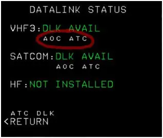
It is via VHF 3 that CPDLC exchanges transit (like AOC - Airline Operation Control exchanges, which allows for example to take ATIS, communicate a message to the company, etc.).
How to use this system with FS2020?
Hoppie's ACARS CDPLC system works with virtual controller systems like IVAO and VATSIM. It can also work autonomously using a small program developed by Hoppie. It is this autonomous system that we will describe here.
To make it work autonomously, you need at least two people and a PC takes the role of ground control. This PC does not need to launch the simulator (unless it wants to follow the plane on a map).
There may of course be several PCs that will launch FS2020 with, for the moment, the A320 from Fenix (or the A32NX from FBW which has some differences, but the process is valid).
For the tutorial, there were two of us (remotely since CPDLC communications go through the Hoppie server)
Prerequisites for the ground controller: from the Hoppie site, load the program onto the PC that will serve as the ground controller.
1 - ACARS ATC (CPDLC): https://www.hoppie.nl/acars/prg/atc/acarsatc-1.5.1-install.exe
2 - That each participant (controller or pilot) has registered with Hoppie (free) and has obtained an identification code. Note that this code must be renewed every 3 months.
Prerequisite for the pilot: you must launch the simulator with the A320 Fenix. Normally the system is used in flight.
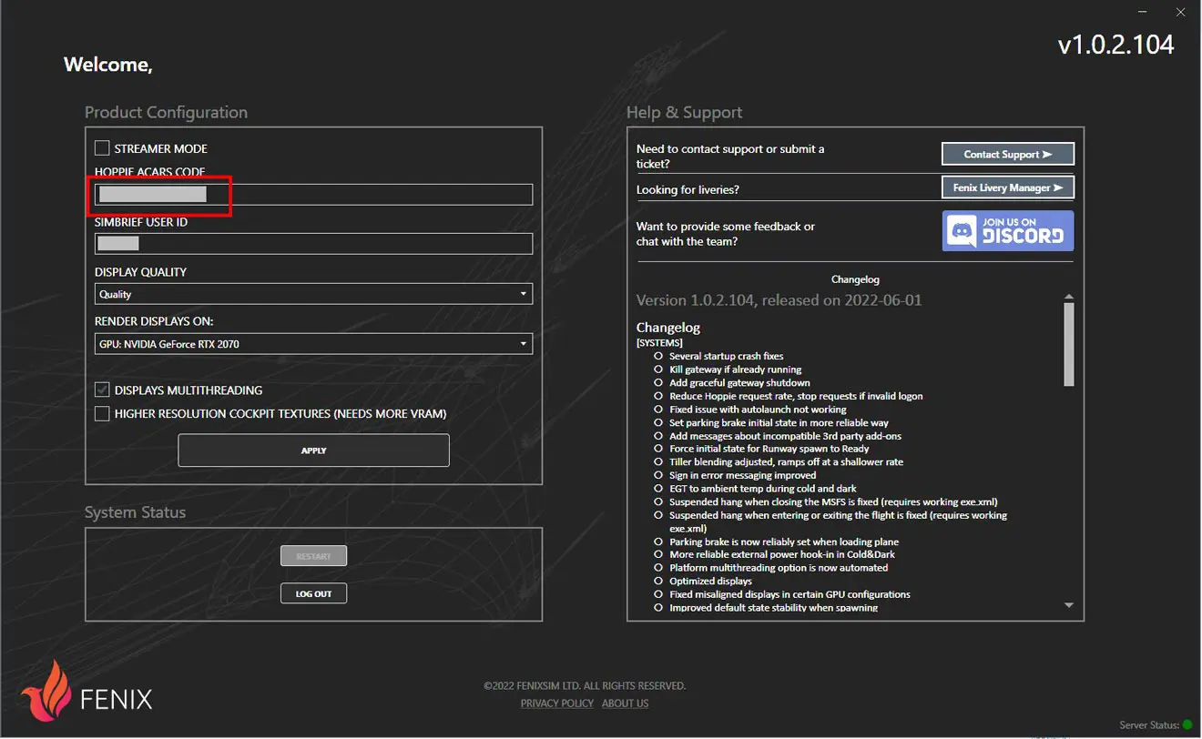
In the EFB, you must have entered your Hoppie code in the external module of the A320 Fenix.
Ground control preparation
1 - Launch the ACARS ATC program on the "controller" PC which opens the window below
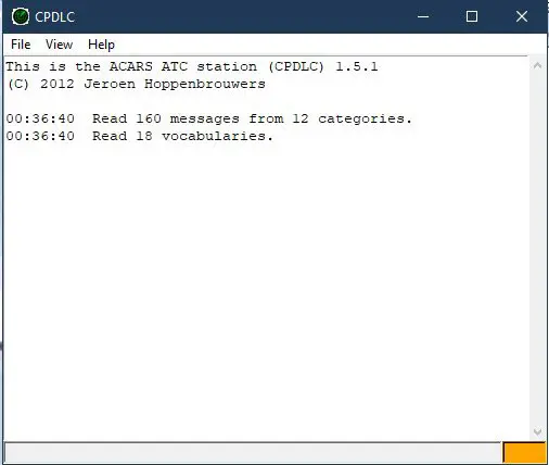
Note: The lower right rectangle changes from orange to green when the link with the Hoppie server is active. It may take more than a minute.
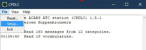
2 - In the top menu, click on "File" then on "Setup" to configure the computer
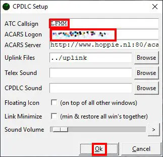
We enter
- the callsign (ATC Callsign) which will be used to call the controller (here LFMM, it is up to the controller).
- his access code to Hoppie (ACARS Logon)
- you can adjust the volume of the sound of the alarms (controller station).
- pressing OK saves the data entered (they are permanent)
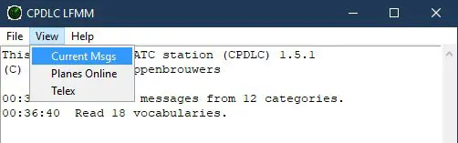
3 - In the top menu, click on "View" then on "Current Msgs" which opens the controller communication window.
4 - Optionally, in the top menu, you can click on "View" then on "Planes Online" to display the window that will allow you to add the callsigns of the planes to call (Add Callsign).
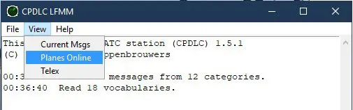
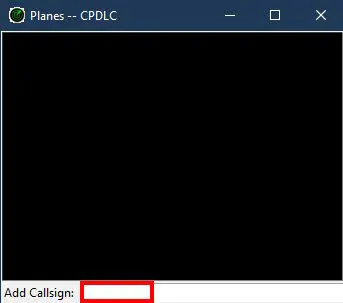
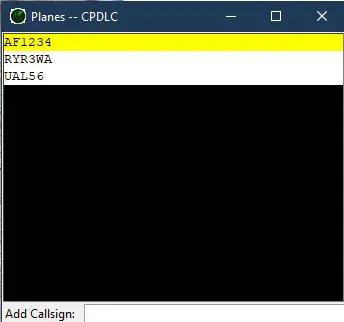
The aircraft to be called have their call signs displayed in the window, just click on it to be able to send them a message.
It is only useful if the controller sends a message on his own initiative (which is not a response to a request from an aircraft).
If there is no communication with an aircraft for approximately 10 minutes, it disappears from the list of aircraft to call.
The main window of the CPDLC program provides the technical follow-up (aircraft registrations, anomalies, alarms sent...).
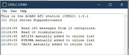
The controller's station is operational and can receive and send messages to the aircraft (or aircraft).
Use
IMPORTANT: the description below only concerns use outside IVAO or VATSIM.
One of the PCs has the role of air traffic controller, the other (or others) are in their A320 Fenix.
For use with ICAO or VATSIM, refer to their documentation.
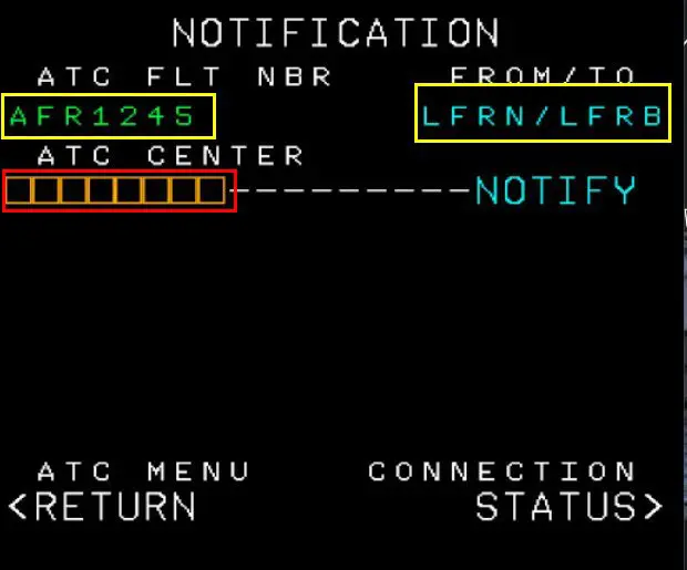
You must have entered your flight plan in the MCDU to have at least the route and the aircraft callsign that were provided in the INIT page (in the example, AFR1245)
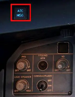
In the plane, everything happens between the MCDU [in red] (the FMS, for the creation of "Downlink" messages [aircraft → control]) and the DCDU [in blue], located just above (which will serve as display and interface) and the audible warning light [in yellow] which warns of the arrival of an "Uplink" message (control → aircraft).
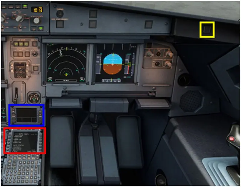
Note that the DCDU turns on by clicking several times on its "BRT" button.
1 - Connection to control
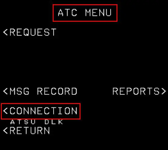
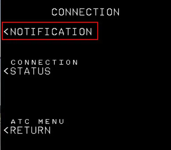
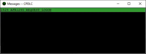
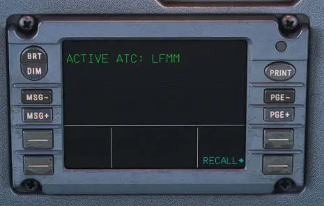
On the plane, to connect to air traffic control (we gave it the callsign LFMM for Marseille [other French control centers are Paris LFFF, Reims LFEE, Brest LFRR and Bordeaux LFBB]) go through the Notification page (ATC COMM button).
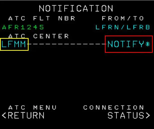
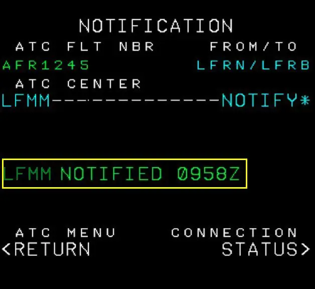
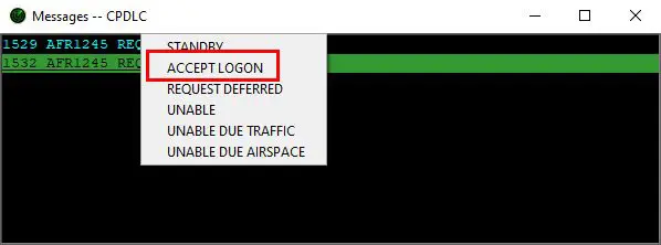
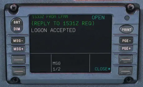
At control, the controller receives the connection request and validates it (left click on the line received).
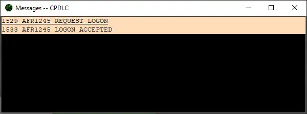
On the plane, on the DCDU the response is displayed. Pressing "CLOSE*" returns to the original message.
2 - In-flight communications: simple pre-formatted response
Example of a flight level change request due to weather.
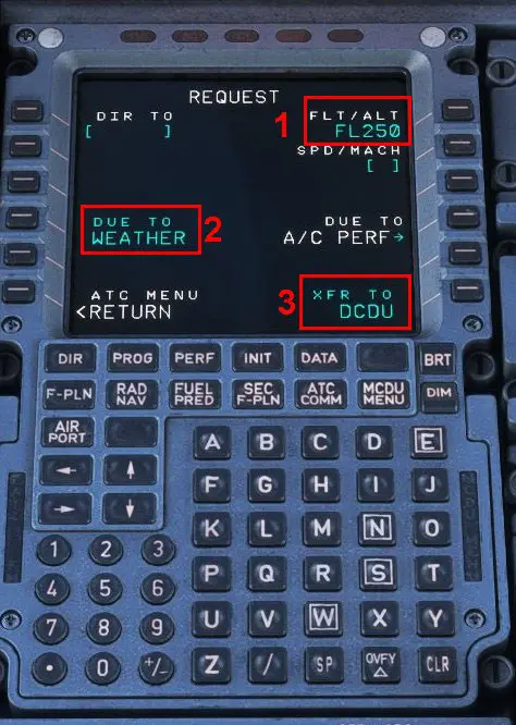
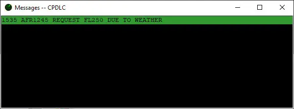
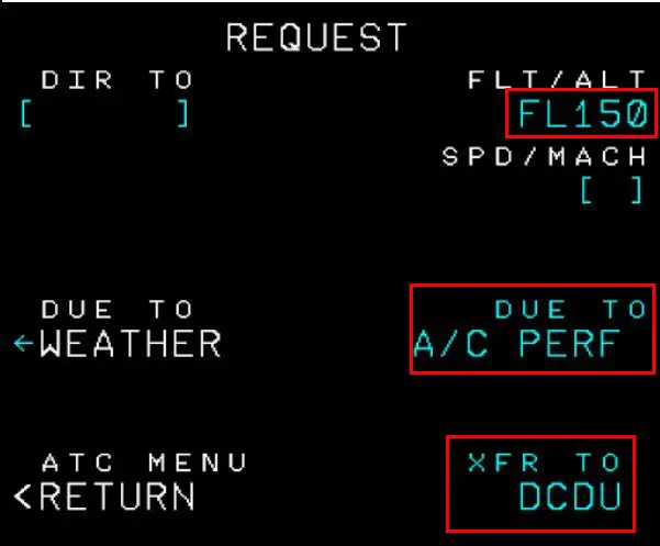
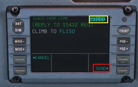
In the plane, press the "ATC COMM" button then the one in front of "REQUEST " to enter the (pre-established) request.
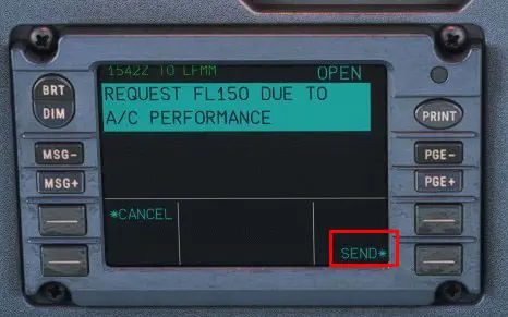
When it is displayed on the DCDU, click on "SEND*" to send it (the sending is acknowledged in the DCDU)
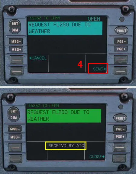
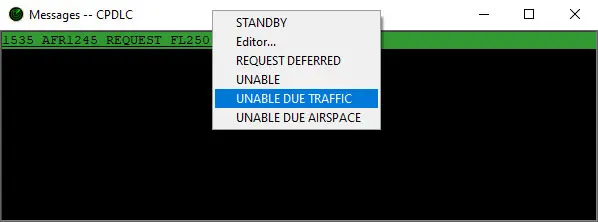
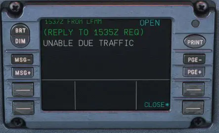
At control, receipt of the request, pre-formatted response (left click on the request line) and sending
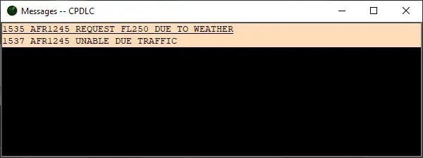
In the plane, after a certain delay (as in reality), an audible and visual alarm is received and the response is displayed on the DCDU. You have to press the alarm button to stop it. (This button is on each side of the panel).
3 - In-flight communication: more complex pre-formatted response
Example of a flight level change request for a technical problem.
On the plane, creation of a request via the "REQUEST" page of the MCDU: it is displayed on the DCDU for sending
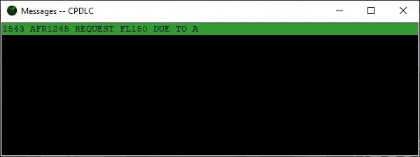
At control, receipt of the request (truncated, small Hoppie anomaly?)
Choice of a more detailed answer with the option "Editor..."
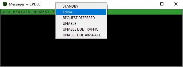
This opens a choice window with selection of the type of response (left column), selection of the response (right column) which is displayed in the first bottom line and addition of manual information.
In our example:
Response type: DESCEND
Pre-formatted response: DESCEND to LEVEL
Added information: FL150 (the aircraft was at FL240).
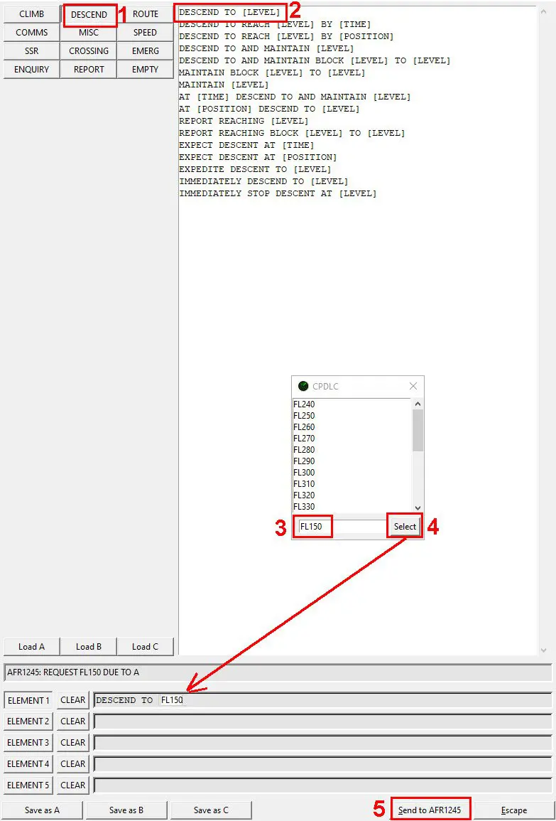
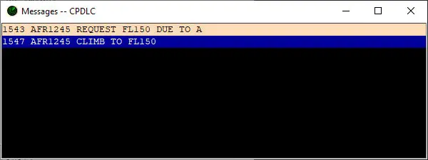
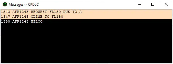
The response is displayed in the communication window of the controller
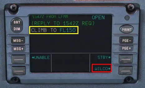
In the plane, the alarm goes off (it must be stopped) and the response is displayed in the DCDU.
It must be acknowledged by pressing "WILCO*" then "SEND*"
At control, reception of the acknowledged message.
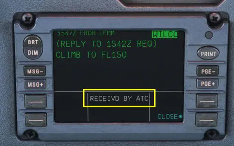
In the plane, display of good reception by control, end of conversation.
Control of multiple planes
As indicated in point 4 of the preparation of the controller position, it is possible to control several aircraft in flight.
The process is the same for each controlled plane, the choice of the plane by the controller is done by clicking on its callsign in the "PLANES CPDLC" window.
The image below gathers the 3 controller windows used to control 2 devices in flight
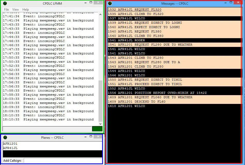
- top left: Hoppie's tracking window (not used for the controller)
- at the bottom left, the controlled aircraft window: click on a line to send a message to the aircraft
- on the right, the window for conversations between the controller and the aircraft. Click on the line you want to answer.
The test planes