A320 Fenix: Landing distance calculation
The A320 Fenix EFB offers a page to calculate its landing distance based on the chosen runway, the expected aircraft weight and the weather.
Calculation page selection
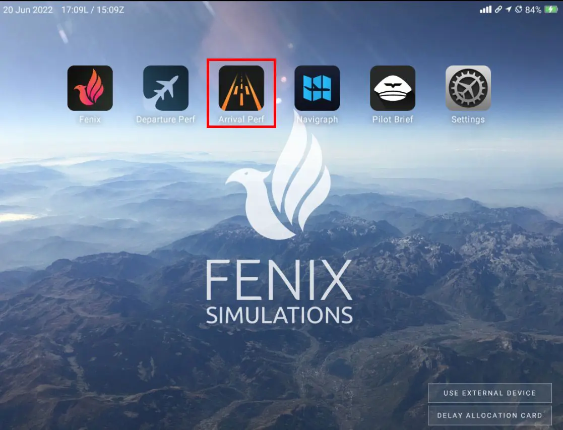
Data entry
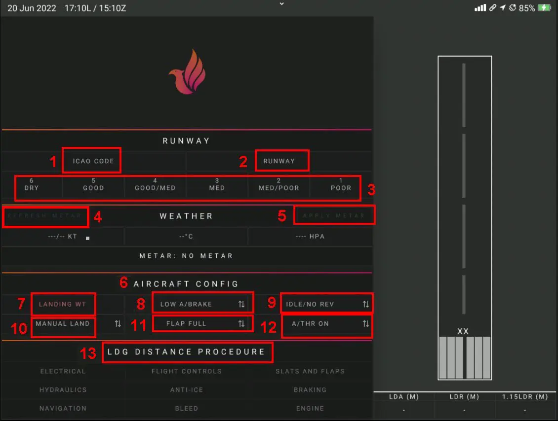
1 – ICAO code of the chosen airport (LFRN, LFRB, LFBO, etc.)
2 – Choice of landing runway
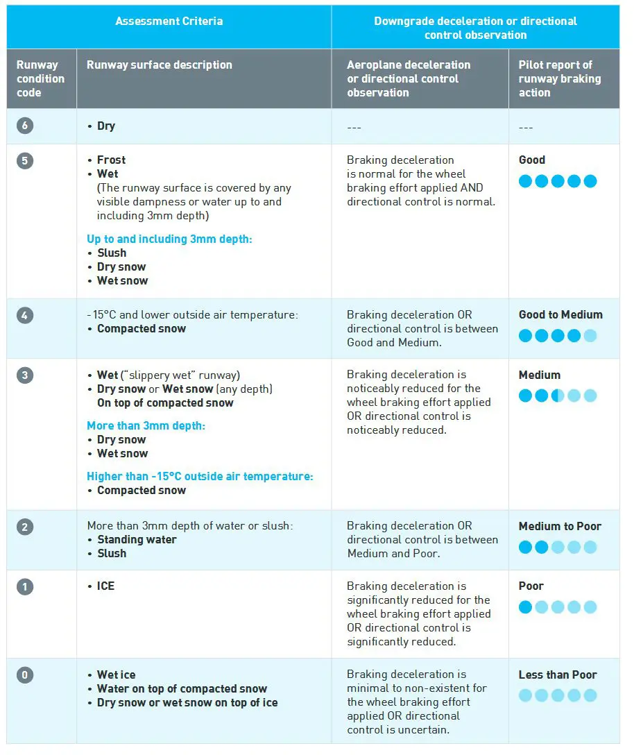
3 – Choice of track braking conditions. They are given in theory in the ATIS within the framework of the GRF, Global Reporting Format, which is a device for harmonizing the system for evaluating and reporting the surface condition of the runway. In France, they can also be retrieved by listening to the ATIS by telephone (number to be retrieved from the field maps). The result is given by group of 3 digits (like 6/6/6 when the track is dry) for the state by 1/3 track.
The correspondence is on the RCAM page at the end of the tutorial.
4 – Weather section to be inserted either manually (with data from the ATIS) or from the latest METAR [5]. It is good practice to take the most recent data (between the ATIS, the METAR and the radio contact with the ATC).
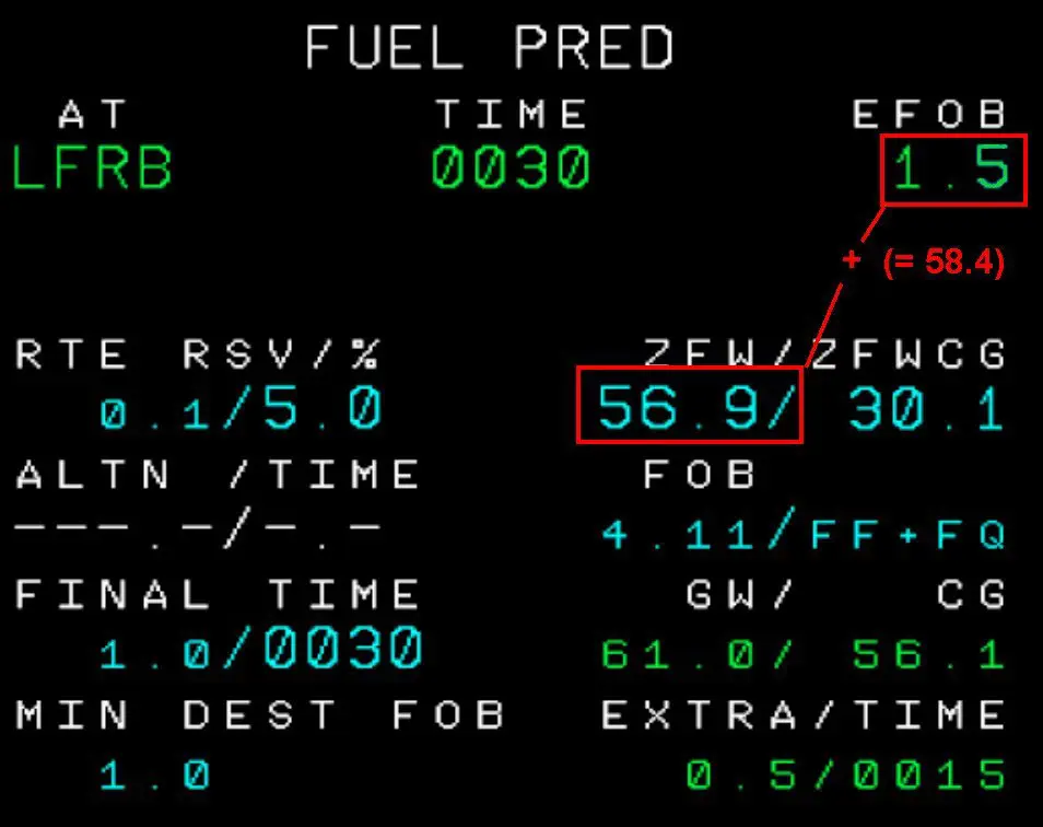
6 – Aircraft configuration: - LANDING WT [7] (Landing Weight: weight of the aircraft planned for landing to be retrieved on the Fuel Pred page and by adding the value of the ZFW [zero fuel Weight = weight of the aircraft for the flight, with crew, passengers, freight but without fuel] and the EFOB [Estimated Fuel On Board] opposite the destination, in the photo example, F-PRED page, 56.9 + 1.5 or 58.4 T).
8 – choice of autobrake: Low or MED
9 – choice of the reverse config: no reverse/reverse Idle or Full Reverse
10 – manual or automatic landing
11 – Flaps configuration: Full or 3
12 – choice of ATHR (on or by hand)
13 – Landing Distance Procedure: choice of a possible failure that could have consequences on the landing distance (flaps that do not extend, a broken hydraulic circuit, etc.).
How do we read the results?
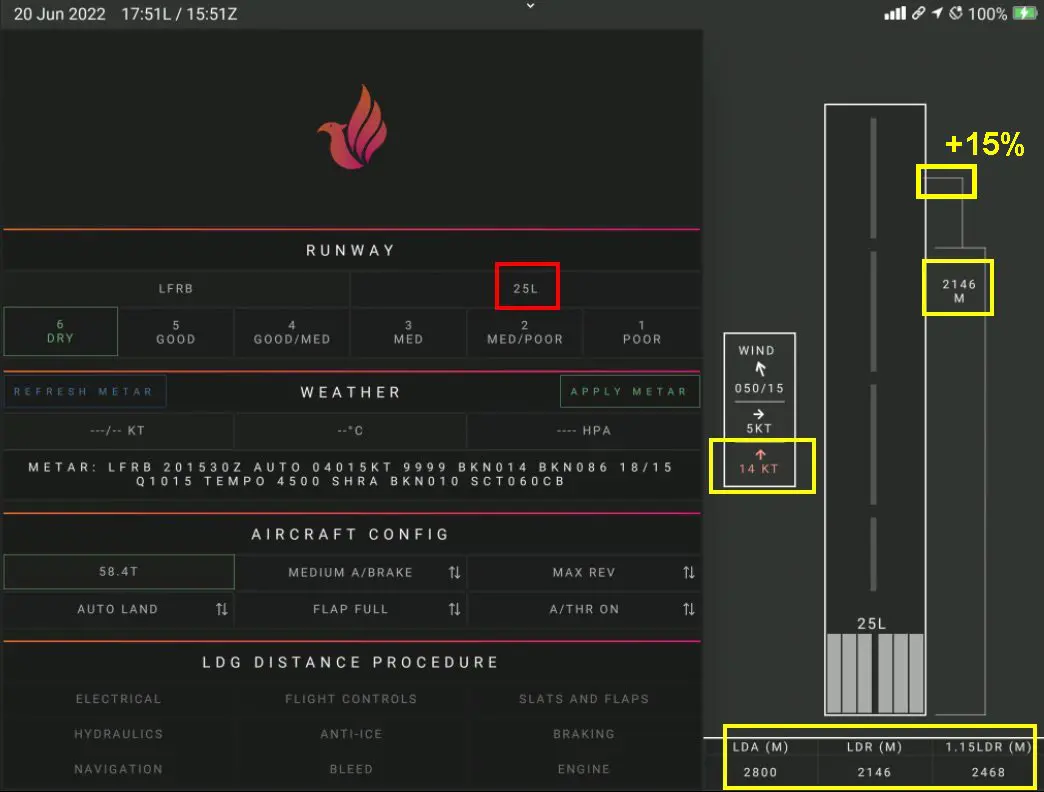
Once all the necessary parameters have been entered, the calculation is automatic and the result is presented on the right side of the screen on the track drawing. We see the wind, its orientation and its cross and face/rear components. Bottom line: Runway length (LDA), landing distance (LDR), then landing distance + 15% (regulatory calculation).
The calculation below shows that the landing distance in 25L is done in limiting conditions because there is a tailwind component of 15 Kt (indicated in red on the left of the runway) which would lengthen the landing distance excessively due to too high ground speed.
Consequently, the pilot will request a landing at 07R which brings the calculated distance from 2146 m to 1750 m, (we also see that the wind component has changed direction).
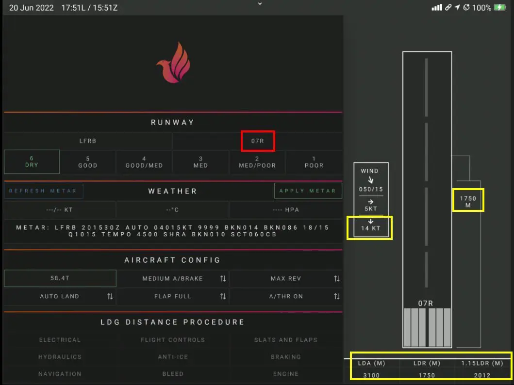
Note: the two calculations show different LDA runway lengths (yellow frame at the bottom of the images) although it is indeed the same runway measured in one direction and the other (3100 m in 07R and 2800 m in 25L).
It's quite simply that at LFRB (Brest Guipavas), there is an offset threshold of 300 m in 25L, which shortens the length available by the same amount.
As mentioned above, filling out this page involves knowing the codes used to indicate the weather quality of the runway.
It is in the file RCAM (Runway Ccondition Assessment Matrix For Landing)
Below is an example of a form found on the ICAO site.