A32NX version DEV: Hydraulic pumps
The developers of the A32NX, the A320 Neo from FlyByWire do a relentless job of realism in the simulation of this aircraft and, icing on the cake, for free.
The "development" version of 03/12/2022 provides a fairly complete simulation of the 3 hydraulic circuits: yellow, blue and green.
With this version, the flight controls only react if the hydraulic circuits are active, that is to say at least one of the engines en route, the APU does not allow it.
For maneuvers with the engine off, the use of electric pumps is also simulated.
A320 hydraulic circuits (origin: https://faq-eng.aviatechno.net/dom/dominique27.php)
The three hydraulic circuits supply the following utilities:
Green circuit:
Orientation of the nose wheels (Tiller, Nose Wheel Streering), landing gear, slats and flaps (Slats & Flaps), reverse engine 1, normal brakes, Yaw Damper n°1 (yaw damper #1), rudder,
rear horizontal stabilizer (THR, Trimmable Horizontal Stabilizer), left elevator, right and left spoiler 1 (3), right and left aileron, right and left spoiler 5, right and left slat brakes
left (WTB, Wing Tips Brakes (4)), right flap brake.
Blue circuit:
Emergency power generation, slats, rudder, right and left flap brakes, right and left slat brakes, right and left elevator, right and left spoiler 3, right and left ailerons.
Yellow circuit:
Alternate brakes, flaps, reverse engine 2, Yaw Damper n°2 (yaw damper #1), rudder, rear horizontal stabilizer, right elevator, spoiler 2 right and left, spoiler 4 right and left,
left flap brakes.
This chapter summarizes the information provided to pilots on these functions
1 - before engine start, APU running, no hydraulics
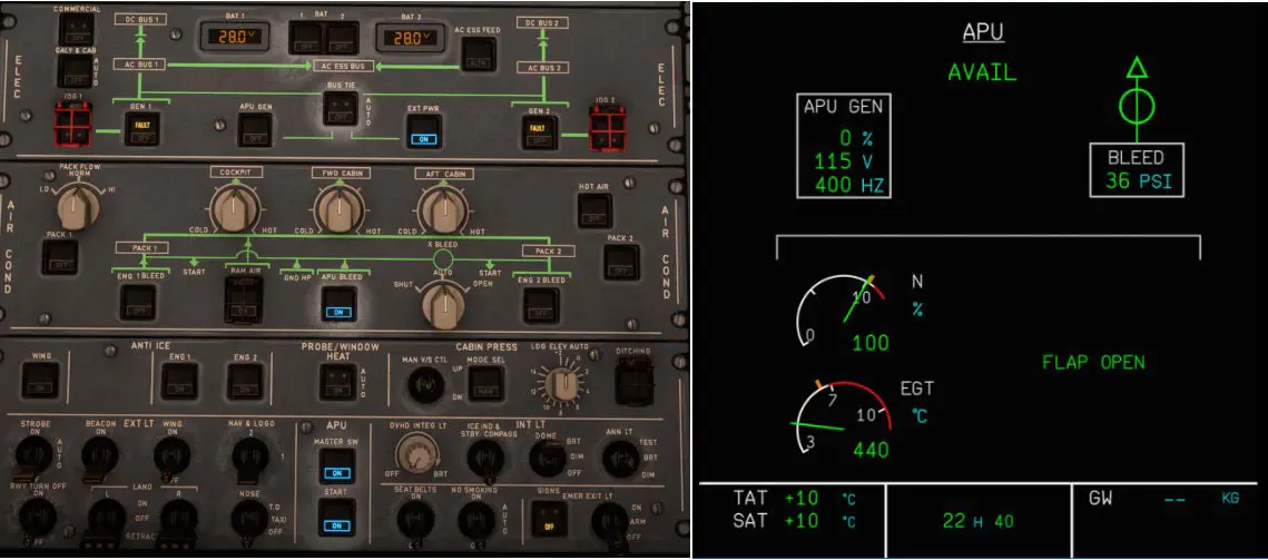
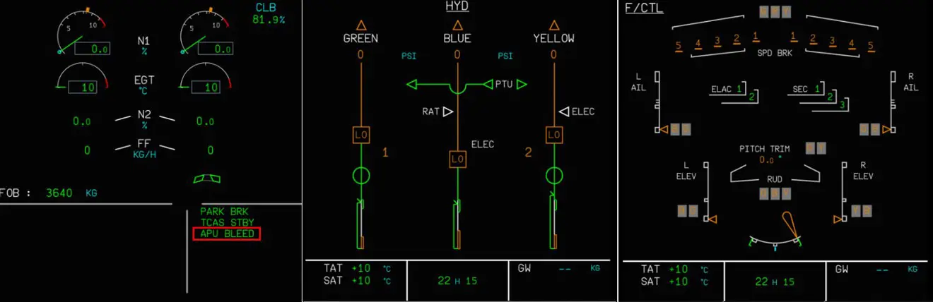
Engines cut, hydraulic circuits closed, controls inactive: everything is "amber" except the PTU (two-way transfer pump between the green and yellow circuits)
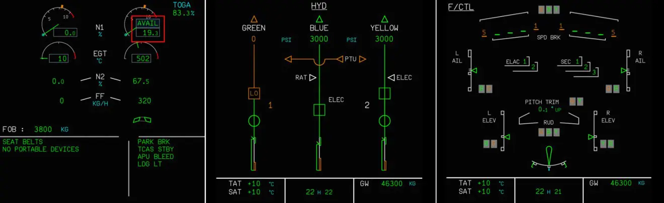
2 - engine #2 is running, the yellow and blue hydraulic circuits are active and allow the use of the flight controls (part of the icons on the graph change to green).
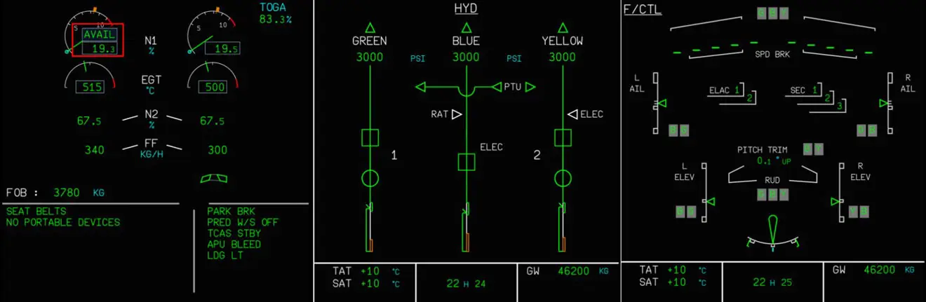
3 - both motors are running, everything turns green and the 3 yellow, blue and green circuits are operational
The FBW team also simulated the two electric pumps (yellow and blue circuits)
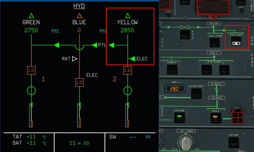
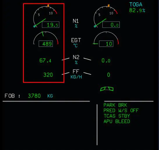
1 - use of the "yellow" electric pump which allows the use of the ground controls when the engines are stopped.
1.1 - start-up of the yellow electric pump and operation of the yellow circuit alone.
Note that, in the "real" world, the "yellow" electric pump is also used to reinflate the braking circuits.
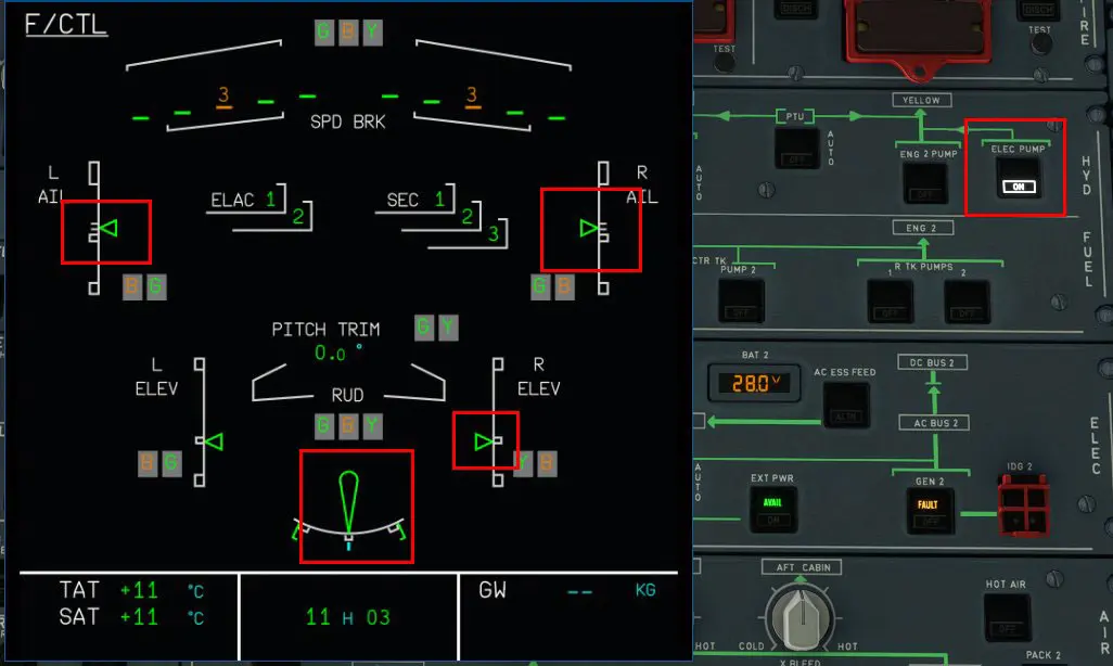
1.2 - the green display of the commands confirms that they are operational.
2 - Another electric pump, that of the blue circuit, exists, it can be used when motor #1 is running alone
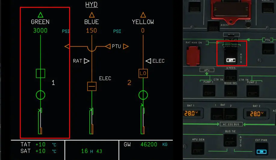
2.1 - engine #1 running
2.2 - Blue electric pump OFF: only green circuit is operational
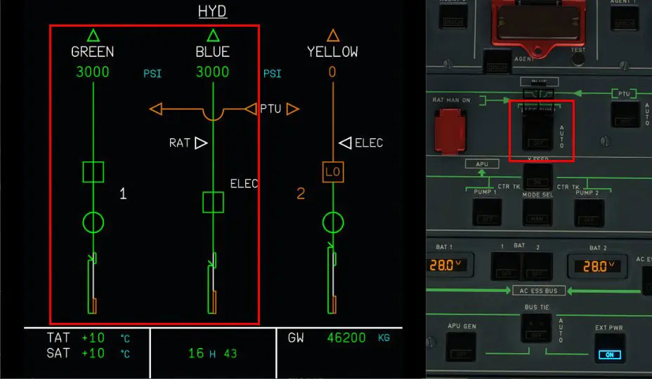
2.3 - blue pump on, the blue circuit is activated
All these new features have an impact on the simulation of the A32NX which may not function correctly if all the hydraulic circuits are not active.
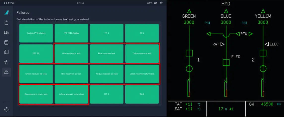
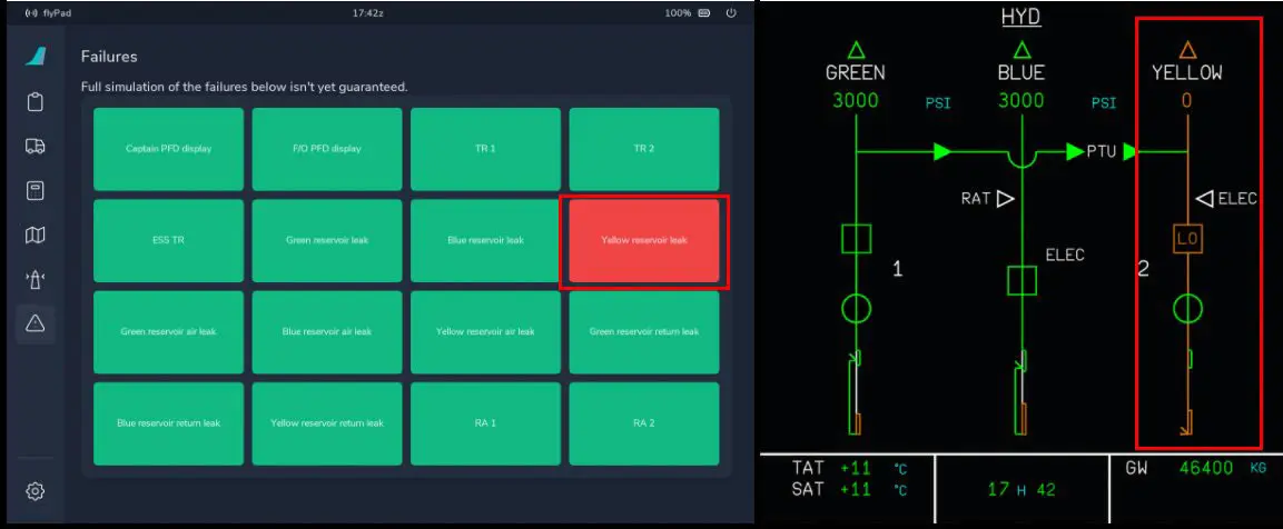
The EFB fault generator has also been updated to integrate faults on these devices as shown in the example below:
1 - no failure, potential failures are circled in red
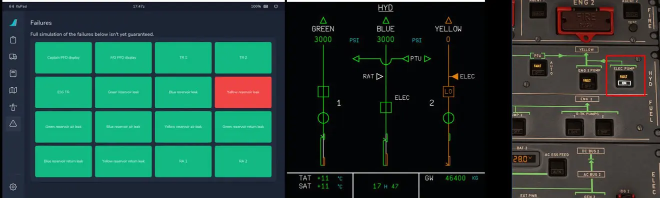
2 - the yellow circuit is faulty (by pressing the corresponding button in the EFB)
3 - yellow circuit faulty, pressing the yellow electric pump puts it in "FAULT"
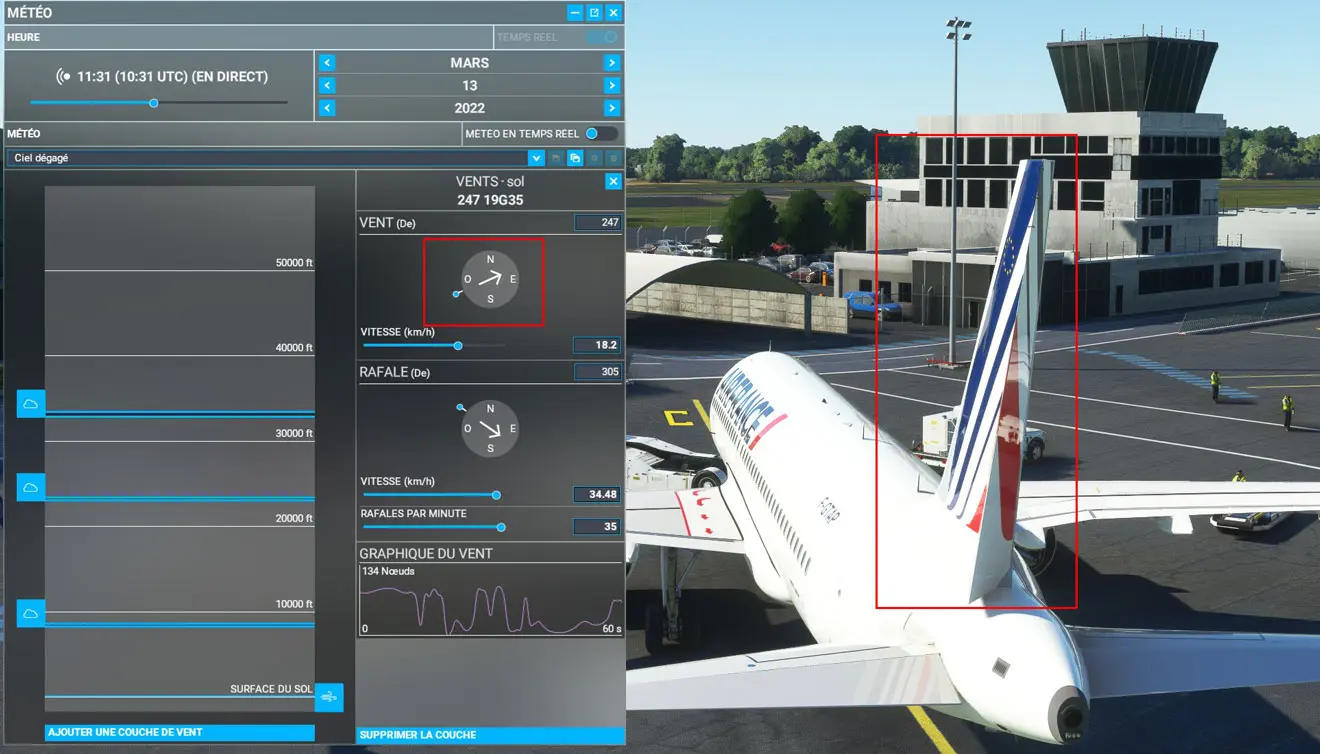
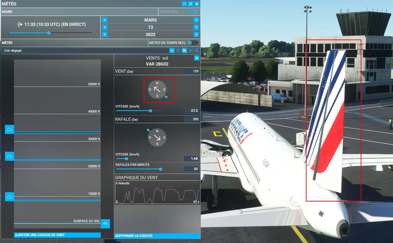
Another new feature, the effect of the wind on the vertical stabilizer
For even more realism, on the ground, with everything off, FBW has simulated the effect of the wind on the vertical stabilizer as shown in these two images: